

Последний
- 01Количественный двухлопастной насос Denison серии Parker T6ED серии Denison
- 02моделей лопастных насосов Parker серии T6EC
- 03моделей лопастных насосов Parker серии T6DC
- 04моделей лопастных насосов Parker серии T6CC
- 05Характеристики и модели лопастных насосов Parker T7B/T7D/T7E
- 06Характеристики и модели лопастных насосов Parker T6C/T6D/T6E

гарантия качества
Широкий ассортимент
Whats app: +86 13728707767
hyd-sales2009@outlook.com
Промышленные новости
ДомашняяПромышленные новостиПодробности
DAIKIN variable piston pump V15 series product manual
Опубликовано: 2026-04-21 11:14:28 Просмотр: 79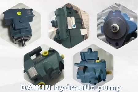
1. Introduction
2. Product Overview & Features
2.1 Product Overview
2.2 Key Features
Low Noise Operation: Achieves low noise performance across the entire pressure range, ensuring a quiet working environment and reducing noise pollution in industrial settings.
High Efficiency: Optimized structural design minimizes power loss, reducing fluid temperature rise and allowing for smaller hydraulic tank designs, which saves installation space and energy consumption.
High Reliability: Equipped with high-responsivity and high-stability components, ensuring long service life and enhancing the reliability of the host equipment it is installed on.
Flexible Control Options: Offers a comprehensive range of control methods, including pressure compensator control, dual pressure control, power-match control, and combination control, to meet different system control requirements.
Versatile Fluid Compatibility: Compatible with petroleum-based hydraulic fluid, water-glycol hydraulic fluid, and phosphate ester hydraulic fluid, adapting to various working conditions.
3. Technical Specifications
Specification Item | V15 | V15 (Type Y) |
|---|---|---|
Theoretical Displacement | 14.8 cm³/rev | 14.8 cm³/rev |
Maximum Operating Pressure | 21 MPa (210 bar) | 7 MPa (70 bar) |
Permissible Rotational Speed | 500 - 1800 min⁻¹ | 500 - 1800 min⁻¹ |
Discharge Rate Adjustment Range (1800 min⁻¹, Axial Port) | 4.5 - 26.6 L/min | 4.5 - 26.6 L/min |
Discharge Rate Adjustment Range (1800 min⁻¹, Side Port) | 7.5 - 26.6 L/min | 4.5 - 26.6 L/min |
Weight (Axial Port) | 12.8 kg | 13.5 kg |
Weight (Side Port) | 14.5 kg | 13.5 kg |
Direction of Rotation (Viewed from Shaft End) | Clockwise (R) or Counterclockwise (L); cannot be changed | Clockwise (R) or Counterclockwise (L); cannot be changed |
Applicable Fluid | Petroleum-based, water-glycol, phosphate ester | Petroleum-based, water-glycol, phosphate ester |
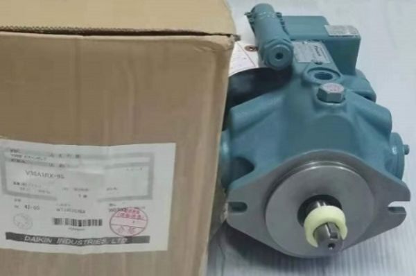
4. Model Nomenclature
V: Series identifier (V Series piston pump)
15: Pump capacity (14.8 cm³/rev)
Control Method I: A (Pressure Compensator Control), C (Combination Control), D (Dual Pressure Control), SA (Power-Match Control)
Pressure Adjustment Range: Specifies the adjustable pressure range (see DAIKIN official pressure adjustment table for details)
Direction of Rotation: R (Clockwise), L (Counterclockwise)
Control Method II: H (Pressure Feedback Method), J (Solenoid Operated Method)
Voltage Code (Solenoid Valve): A (AC 100V/110V), B (AC 200V/220V), N (DC 12V), P (DC 24V)
Piping Direction: No designation (Axial Port), X (Side Port)
Design No.: 95 (Applicable for V15 and V38 models); subject to change without prior notice
5. Installation Instructions
5.1 Installation Precautions
The pump must be installed by qualified and authorized personnel in accordance with this manual. Improper installation may cause equipment damage, fluid leakage, or personal injury.
Choose a clean, dry, and well-ventilated installation location, away from flammable materials, high-temperature heat sources, and direct sunlight. Ensure there is sufficient space around the pump for operation, maintenance, and ventilation.
The installation surface must be strong enough to withstand the pump’s weight and operating vibration. Use appropriate fixing bolts to secure the pump firmly to avoid vibration during operation, which may damage the pump or pipeline connections.
Before installation, check the pump for any damage during transportation (e.g., cracks, loose parts). Clean the pump inlet and outlet ports to prevent debris from entering the pump and causing internal wear.
Ensure the piping direction (axial or side port) matches the model’s configuration. Use clean, high-quality hydraulic pipes and fittings, and ensure tight connections to avoid fluid leakage. The pipeline should be arranged smoothly to minimize pressure loss and vibration.
5.2 Installation Steps
Position the pump on the installation surface, align the mounting holes with the pre-drilled holes on the base, and secure the pump with fixing bolts. Tighten the bolts evenly to ensure the pump is installed stably and horizontally.
Connect the hydraulic pipeline to the pump’s inlet and outlet ports. Use appropriate gaskets to ensure a tight seal. Avoid over-tightening the fittings, which may damage the threads or seals.
Connect the electrical wiring (if applicable) according to the control method and voltage requirements. Ensure the wiring is correct and secure to avoid electrical faults, short circuits, or electric shock.
Fill the hydraulic system with the recommended hydraulic fluid (refer to Section 7.1) to the specified level. Bleed the air from the pipeline and pump to prevent cavitation and ensure smooth operation.
Check all connections (pipeline, electrical, and mechanical) for tightness and correctness. Rotate the pump shaft manually to ensure it rotates flexibly without jamming or abnormal resistance.
6. Operation Instructions
6.1 Pre-Operation Check
Check the hydraulic fluid level in the tank. Ensure the fluid level is within the specified range (between the minimum and maximum marks). If the fluid level is too low, add the recommended hydraulic fluid immediately.
Check the hydraulic fluid for contamination, discoloration, or deterioration. If the fluid is dirty or has a abnormal odor, replace it with new fluid and clean the filter.
Inspect all pipeline connections for fluid leakage. Tighten any loose fittings immediately.
Check the pressure adjustment settings to ensure they match the system requirements. Adjust the pressure compensator or control valve according to the application needs (refer to the control method instructions in Section 4).
Ensure the power supply is stable and the electrical connections are secure. Check the direction of rotation to confirm it matches the pump’s specified direction (R or L).
6.2 Start-Up Operation
Turn on the power supply and start the pump at a low speed. Run the pump idly for 2-3 minutes to allow the hydraulic fluid to circulate and the pump to warm up.
Gradually increase the pump speed to the rated speed. Monitor the pump’s operating status, including noise, vibration, and fluid temperature. The normal operating temperature of the hydraulic fluid should be between 30°C and 60°C.
Check the system pressure and flow rate. Adjust the control valve or displacement regulator to achieve the required pressure and flow for the application. Ensure the pressure does not exceed the pump’s maximum operating pressure (refer to Section 3).
During the initial operation, observe the pump for any abnormal phenomena (e.g., excessive noise, fluid leakage, overheating). If any abnormality is found, stop the pump immediately and troubleshoot (refer to Section 8).
6.3 Normal Operation
Maintain the pump’s operating speed within the permissible range (500-1800 min⁻¹) to avoid damage to the pump’s internal components.
Regularly monitor the hydraulic fluid temperature. If the temperature exceeds 60°C, check the cooling system and ensure it is working properly. Overheating may cause fluid deterioration and pump damage.
Do not adjust the pressure or flow settings arbitrarily during operation unless necessary. Any adjustment should be made gradually to avoid sudden pressure spikes, which may damage the system or pump.
Avoid operating the pump under no-load conditions for an extended period, as this may increase power consumption and reduce the pump’s service life.
6.4 Shutdown Operation
Gradually reduce the pump speed to a low speed and run idly for 1-2 minutes to cool down the pump and hydraulic fluid.
Turn off the power supply to stop the pump.
Close the main valve of the hydraulic pipeline to prevent fluid backflow.
After shutdown, check the pump and pipeline for fluid leakage, and clean the pump surface if necessary. Record the operating time and any abnormal phenomena for future reference.
Связанные
 +86 13728707767
  +86 13728707767